Transformer: What is it? (Definition And Working Principle)
A transformer is a passive component that transfers electrical energy from one electrical circuit to another circuit, or multiple circuits,, either increasing (stepping up) or reducing (stepping down) the voltage.


Working Principle of Transformer
The working principle of a transformer is very simple. Mutual induction between two or more windings (also known as coils) allows for electrical energy to be transferred between circuits. This principle is explained in further detail below.
A transformer works on the principle of electromagnetic induction, which states that a current-carrying conductor produces a magnetic field around it and vice-versa. A transformer consists of two sets of wires:
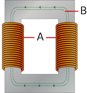
- Primary winding (A): collects power
- Secondary winding (B): provides power
The primary and secondary windings are wound together on a magnetic iron circuit core, but these coils are not in contact with one another, as seen in Figure . The core is made of a soft magnetic material consisting of laminations linked together to help reduce core loss. Core loss is the energy loss within the core caused by an alternating magnetic flux. An unstable magnetic field eventually destroys the core material's functioning.
When the primary winding is connected to an alternating power supply, current flows through the coil, and a magnetic flux is induced. A part of this magnetic field links with the secondary windings by mutual induction, thereby producing a current flow and voltage at the secondary (load) side. The voltage produced at the load side is proportional to the number of turns in the secondary winding relative to that in the primary side. The voltage and current transformation are given by:
V1 / V2 = N1 / N2 = I2 / I1
- V1: Voltage applied to the transformer primary winding
- V2: Voltage produced at the secondary (load) winding of the transformer
- N1: Number of turns in the primary winding
- N2: Number of turns in the secondary winding
- I1:Current in the primary winding
 and secondary windings (B) of a transformer wound on a magnetic core(C)") |
| Primary windings (A) and secondary windings (B) of a transformer wound on a magnetic core(C) |
Transformer construction
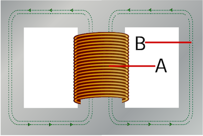
- Core type transformer: In a core-type transformer, the primary and secondary coils are wound outside and surround the core ring, as seen in Figure .
- Shell type transformer: In a shell-type transformer, the primary and secondary windings pass inside the magnetic steel core, forming a shell around the windings, as seen in Figure
Transformer core construction :
In the core type transformer construction, one-half of the winding is wrapped around each leg (or limb) of the transformer’s magnetic circuit . Half of the secondary winding and half of the primary winding are placed one over the other concentrically on each leg. This facilitates an increased magnetic coupling between the windings. This allows practically all magnetic lines of force to pass both the primary and secondary windings simultaneously. However, with this type of transformer construction, a small percentage of the magnetic lines of force flow outside of the core (known as leakage flux).
The cylindrical coils have different layers, and each layer is insulated from the other. Materials like paper, cloth, or mica are commonly used for insulation. Low voltage windings are placed adjacent to the core, as they are easier to insulate.
Shell type transformers
In a shell-type transformer, the primary and secondary coils are wound and mounted in layers stacked with insulation between them (Figure 4 labeled A). Both the primary and secondary windings are wound on the same center limb or leg, which has twice the cross-sectional area of the two outer limbs. A proper insulating medium separates both the windings. As primary and secondary coils are wound close together, a shell-type transformer has the advantage of decreasing core losses and increasing overall efficiency.
Electrical transformer types
Core-type transformer and shell-type transformer
Based on construction, transformers are classified into core-type transformers and shell-type transformers.
Step-up transformer and step-down transformer
Based on their purpose, transformers are classified into step-up transformers and step-down transformers.
- A step-up transformer increases the voltage at the secondary windings with respect to that on the primary side (with a subsequent decrease in current).
- A step-down transformer decreases the voltage at the secondary windings with respect to that on the primary side (with a subsequent increase in current).
Single-phase transformer and three-phase transformer
Based on power supply, transformers are classified into single-phase transformers and three-phase transformers. Single-phase transformers work on a single-phase power supply, whereas a three-phase transformer works on a three-phase power supply.
Power transformer, distribution transformer, and instrumentation transformer
Based on their use, transformers are classified into:
- Power transformer: A power transformer is a conventional high-rating transformer used in transmission networks.
- Distribution transformer: A distribution transformer or service transformer is a transformer that provides the final voltage transformation in the electric power distribution system. These transformers step down the voltage used in distribution lines to the level used by the customer.
- Instrumentation transformer: Instrument transformers provide insulation and protection in relays and commercial metering devices. These transformers also measure a very high voltage that cannot be measured by a conventional voltmeter. There are two types of instrument transformers, namely current transformer, and voltage transformer.
What is a transformer used for?
Transformers have two primary functions: Voltage transformation and isolation:
- The voltage of the secondary can be higher or lower than the voltage that drives the primary and is determined by the ratio of turns of wire in the two coils.
- Isolation refers to the fact that the coils are connected only by a magnetic field, so they can be independent of a common ground.
Primary applications are for power and for signal isolation / impedance transformation.
An autotransformer is a transformer with a single coil with intermediate "taps" to effect the changed outgoing voltages. They do not provide isolation.
Transformer capacity is rated in kilovolt-amps (KVA): The volts x amps / 1000.
0
Post a Comment
Do leave your comments.