Logic Gates
A logic gate is a device that acts as a building block for digital circuits. They perform basic logical functions that are fundamental to digital circuits. Most electronic devices we use today will have some form of logic gates in them. For example, logic gates can be used in technologies such as smartphones, tablets or within memory devices.
Logic gates are the basic building blocks of any digital system. It is an electronic circuit having one or more than one input and only one output. The relationship between the input and the output is based on a certain logic. Based on this, logic gates are named as AND gate, OR gate, NOT gate etc.
AND Gate
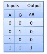
A circuit which performs an AND operation is shown in figure. It has n input (n >= 2) and one output.
Function: The AND gate gives a high output (1) only when all inputs are high (1). If any input is low (0), the output is low (0).

Logic diagram

Truth Table
OR Gate
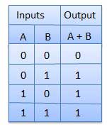
A circuit which performs an OR operation is shown in figure. It has n input (n >= 2) and one output.
Function: The OR gate gives a high output (1) if at least one input is high (1). The output is low (0) only when both inputs are low (0)
Logic diagram

Truth Table
NOT Gate
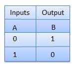
NOT gate is also known as Inverter. It has one input A and one output Y.
- Function: The NOT gate is also known as an inverter. It gives a high output (1) if the input is low (0) and a low output (0) if the input is high (1).

Logic diagram

Truth Table
NAND Gate
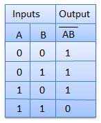
A NOT-AND operation is known as NAND operation. It has n input (n >= 2) and one output.
- Function: The NAND gate is the inverse of the AND gate. It gives a high output (1) unless all inputs are high (1), in which case the output is low (0).

Logic diagram

Truth Table
NOR Gate
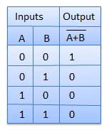
A NOT-OR operation is known as NOR operation. It has n input (n >= 2) and one output.
Function: The NOR gate is the inverse of the OR gate. It gives a high output (1) only when both inputs are low (0). If any input is high (1), the output is low (0).

Logic diagram

Truth Table
XOR Gate
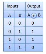
XOR or Ex-OR gate is a special type of gate. It can be used in the half adder, full adder and subtractor. The exclusive-OR gate is abbreviated as EX-OR gate or sometime as X-OR gate. It has n input (n >= 2) and one output.

Logic diagram

Truth Table
XNOR Gate
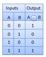
XNOR gate is a special type of gate. It can be used in the half adder, full adder and subtractor. The exclusive-NOR gate is abbreviated as EX-NOR gate or sometime as X-NOR gate. It has n input (n >= 2) and one output.

Logic diagram

Truth Table
Application of Logic Gates
Logic gates have a lot of applications, but they are mainly based on their mode of operations or their truth table. Basic logic gates are often found in circuits such as safety thermostats, push-button locks, automatic watering systems, light-activated burglar alarms and many other electronic devices.
One of the primary benefits is that basic logic gates can be used in various combinations if the operations are advanced. Besides, there is no limit to the number of gates that can be used in a single device. However, it can be restricted due to the given physical space in the device. In digital integrated circuits (ICs), we will find an array of the logic gate area unit.
0
Post a Comment
Do leave your comments.